Car Problems
Variable Valve Timing Solenoid – Symptoms, Location, Function & Replacement Cost
The variable valve timing solenoid is one part that enables modern engines to offer the ideal mix between power, fuel efficiency, and low emissions. This tiny but crucial component regulates the opening and closing of engine valves, enabling the engine to adjust to various operating circumstances. The variable valve timing solenoid works in the background to maximize engine performance in real time, whether you’re speeding on the highway or idling in traffic.
Manufacturers have depended more and more on Variable Valve Timing (VVT) systems as automobiles have developed to meet stringent emission regulations while enhancing drivability.
By controlling oil flow to the camshaft and guaranteeing accurate valve timing based on engine speed, load, and temperature, the VVT solenoid directly contributes to this process. Drivers benefit from improved fuel economy, less engine strain, and smoother acceleration when the solenoid is operating properly.
However, observable performance problems like rough idling, poor acceleration, decreased fuel efficiency, and an illuminated check engine light might result from a variable valve timing solenoid failing or becoming blocked.
Many car owners ignore the solenoid until the problem gets worse since these symptoms frequently coexist with other engine issues. You can maintain your engine operating efficiently and avoid expensive repairs by being aware of the symptoms, operation, and maintenance needs of the variable valve timing solenoid.

What Is a Variable Valve Timing Solenoid?
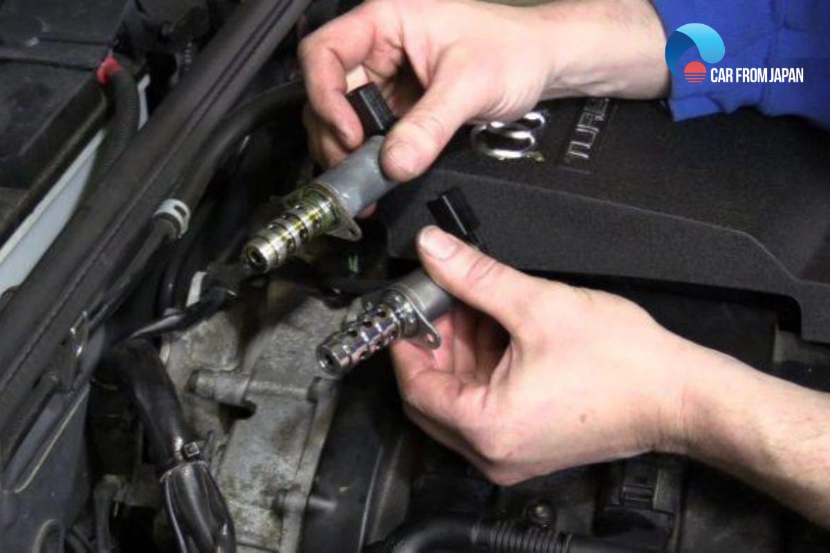
An electronically controlled valve that controls the flow of engine oil to the camshaft actuator is known as a variable valve timing solenoid, or VVT solenoid. Its main function is to modify valve timing in response to current driving conditions, enabling the engine to run effectively at both low and high speeds. The solenoid helps advance or delay the opening and shutting of engine valves by regulating oil pressure, which enhances emissions, fuel economy, and power delivery.
The engine control unit (ECU) and the VVT solenoid collaborate closely. The ECU transmits an electrical signal to the solenoid in response to variations in engine load, throttle position, speed, or temperature. The solenoid responds by opening or closing internal channels that supply the camshaft phaser with pressurized oil. By changing the camshaft position, the engine may optimize valve timing without the need for mechanical assistance.
While many engines use two or more VVT solenoids, usually one for the intake camshaft and another for the exhaust camshaft, the majority of contemporary cars employ at least one. The fundamental purpose is the same regardless of variations in manufacturer designs, such as Toyota’s VVT-i, Honda’s VTEC, or BMW’s VANOS. The variable valve timing solenoid is essential for smooth engine operation, enhanced performance, and long-term engine health because it guarantees accurate valve control.
Read also: Cylinder Head Temperature Sensor: Function, Symptoms & Replacement Cost
How a Variable Valve Timing Solenoid Works
By precisely regulating engine oil flow to the camshaft, the variable valve timing solenoid enables dynamic valve timing changes in response to changing driving conditions. Modern engines rely on the VVT solenoid to continuously modify valve operation for improved economy, power, and emissions management, in contrast to previous engines with set valve timing.
Role of Engine Oil Pressure
The VVT system depends on engine oil pressure. Oil is pumped through internal channels to the variable valve timing solenoid when the engine is operating. As a gatekeeper, the solenoid opens or closes oil flow in response to ECU directives. Oil travels to the camshaft phaser after passing through the solenoid, where hydraulic pressure causes the camshaft to move slightly in order to advance or delay valve timing.
Oil quality and viscosity are important since oil pressure is crucial to this process. Low oil levels, sludge accumulation, or dirty oil can limit flow and result in improper or delayed valve timing. Because of this, one of the most frequent causes of a variable valve timing solenoid failing or starting to malfunction is improper oil maintenance.
ECU Control and Timing Adjustment
Engine speed, throttle position, camshaft position, crankshaft position, and coolant temperature are just a few of the sensors that the engine control unit (ECU) continuously monitors. The ECU uses this information to calculate the ideal valve timing for the present driving circumstances. The variable valve timing solenoid is then instructed to modify oil flow by means of an electrical signal.
To increase idle stability and fuel efficiency at low engine speeds, the ECU may instruct the solenoid to delay valve timing. The ECU advances valve timing to maximize power production by increasing airflow into the engine at higher speeds or during strong acceleration. The engine may provide smooth performance without the driver sensing any mechanical changes because to this smooth adjustment, which takes place in milliseconds.
Types of Variable Valve Timing Systems
Manufacturers employ various system designs to accomplish variable valve timing, even though the fundamental objective is the same for all vehicles. Although the names, levels of sophistication, and methods of operation can differ, all systems use variable valve timing solenoids to control oil flow and modify camshaft timing. The widespread use of VVT solenoids in contemporary engines can be explained by an understanding of these systems.
Traditional VVT Systems
One or two solenoids are used in basic VVT systems to regulate camshaft timing. These systems improve performance at higher RPMs and fuel efficiency at lower RPMs by progressively adjusting valve timing dependent on engine speed and load. They provide a mix between simplicity and efficacy and are frequently found in many mid-range and economical cars.
VVT-i (Variable Valve Timing – Intelligent)
Toyota created VVT-i, which optimizes intake valve timing using electronically controlled solenoids. For smoother acceleration, improved fuel efficiency, and lower emissions, the technology continuously modifies the camshaft position. Dual VVT-i, which regulates both intake and exhaust camshafts for even higher efficiency, is another feature of some sophisticated Toyota engines.
VTEC (Variable Valve Timing and Lift Electronic Control)
Honda’s VTEC system modifies valve lift and duration in addition to valve timing. VVT solenoids are crucial because they regulate oil flow, which activates various camshaft profiles, even though VTEC uses mechanical parts in addition to oil pressure. Strong high-RPM performance without compromising low-speed efficiency is a well-known feature of this technology.
VANOS (Variable Nockenwellen Steuerung)
To modify camshaft timing, BMW’s VANOS system mostly depends on solenoid control and oil pressure. Double VANOS modifies both the intake and exhaust camshafts, whereas single VANOS only modifies one. This technology improves fuel economy, torque, and throttle responsiveness, particularly over a large RPM range.
MultiAir and Dual VVT Systems
Electronically controlled solenoids are used in advanced systems, such as Fiat’s MultiAir and other twin VVT configurations, to more precisely control valve timing. Independent intake and exhaust management made possible by these technologies results in increased combustion efficiency, reduced emissions, and more seamless engine performance.
Read also:Engine Mount Replacement Cost
Variable Valve Timing Solenoid Location
Usually found on or close to the engine’s cylinder head, the variable valve timing solenoid regulates the camshaft. Because of its location, it can control oil flow straight to the camshaft phaser, guaranteeing quick and precise valve timing adjustments. Compared to many internal engine components, the solenoid is typically easy to access, albeit the precise location varies depending on the vehicle make and engine design.
The VVT solenoid is installed on the top or front of the cylinder head in the majority of inline engines, frequently close to the valve cover. Two solenoids—one for the intake camshaft and another for the exhaust camshaft—are typically seen in engines with dual VVT systems. In order to facilitate identification during inspection or replacement, these are frequently labeled or placed side by side.
Variable valve timing solenoids are usually found on each cylinder bank of V-type engines (V6 or V8). This implies that depending on whether the engine regulates the intake, exhaust, or both camshafts, there can be more than one solenoid. The majority of solenoids may be easily diagnosed, cleaned, or replaced because they are fastened with one or two bolts and connected via an electrical connector and oil route.
Symptoms of a Bad Variable Valve Timing Solenoid
Engine performance problems may become apparent if the variable valve timing solenoid fails. Any defect impacts how the engine breathes because it directly regulates camshaft timing, resulting in symptoms that are frequently difficult to ignore. Early detection of problems can help save costly repairs and major engine damage.
Check Engine Light
An illuminated check engine light is one of the most typical indicators of a malfunctioning VVT solenoid. Solenoid operation is continuously monitored by the ECU, which initiates a fault code (often P0010, P0011, or P0020) if it finds anomalies. Ignoring this warning could result in more engine issues.
Rough Idling
The engine may idle unevenly or roughly due to a malfunctioning solenoid. The air-fuel combination is disrupted by improper valve timing, which causes vibrations, stalling, or uneven RPMs when the vehicle is stationary.
Poor Acceleration
The engine may feel slow or unresponsive if the solenoid is unable to modify valve timing during acceleration. During highway merging or overtaking, drivers may experience a delayed throttle response, trouble achieving higher RPMs, or an overall lack of power.
Engine Stalling
In extreme circumstances, the engine may stall due to a defective VVT solenoid, particularly when slowing down or stopping. This happens because smooth combustion is disrupted by the camshaft timing’s inability to adjust to low RPM conditions.
Reduced Fuel Efficiency
Engine efficiency is reduced by improper valve timing, which frequently results in higher fuel consumption. Despite having regular driving habits, drivers may realize that they are filling up the tank more frequently.
Rattling or Ticking Noise
The engine may make metallic ticking or rattling noises due to a failed solenoid. This noise is caused by internal solenoid problems or insufficient oil flow, which makes it difficult for the camshaft phaser to maintain correct timing.
Common Trouble Codes Related to VVT Solenoid
The engine control unit (ECU) produces diagnostic trouble codes (DTCs) to identify a malfunctioning variable valve timing solenoid. Knowing these codes can assist pinpoint the precise problem and direct appropriate repair.
P0010 – “A” Camshaft Position Actuator Circuit (Bank 1)
This code indicates a malfunction in the VVT solenoid circuit for the intake camshaft on Bank 1. It could result from electrical issues, a stuck solenoid, or sludge buildup blocking oil flow. Symptoms often include rough idling, reduced fuel efficiency, and a check engine light.
P0011 – “A” Camshaft Position – Timing Over-Advanced
This code occurs when the ECU detects the intake camshaft is timed too far ahead. Possible causes include a faulty solenoid, low oil pressure, or dirty oil passages. Drivers may notice poor acceleration or engine knocking.
P0012 – “A” Camshaft Position – Timing Over-Retarded
P0012 signals the camshaft is lagging behind the expected position, often due to a solenoid that isn’t opening correctly or oil flow restrictions. Symptoms are similar to P0011 but may also include stalling at idle.
P0020, P0021, P0022 – Bank 2 Codes
These codes mirror P0010–P0012 but refer to Bank 2 camshafts, commonly found in V6 or V8 engines. Issues with Bank 2 solenoids can cause similar performance problems as Bank 1, including uneven idle, decreased fuel economy, and engine noise.
Why Trouble Codes Matter
Because incorrect valve timing exerts additional strain on pistons, valves, and timing components, ignoring these errors can cause long-term engine damage. Optimal engine performance and lifetime are ensured by routinely checking for codes and quickly fixing them.
Causes of Variable Valve Timing Solenoid Failure
A variable valve timing solenoid may malfunction for a number of reasons, most frequently related to component wear, engine conditions, or maintenance practices. Finding these factors extends engine life and helps avoid reoccurring problems.
Dirty or Low Engine Oil
Inadequate or dirty oil is the most frequent reason for VVT solenoid failure. Sludge, dirt, or low oil levels can interfere with the solenoid’s proper operation because it depends on oil pressure. This may eventually result in the solenoid sticking and improper valve timing.
Sludge Buildup
Sludge frequently forms in the oil channels of engines with infrequent oil changes. This accumulation may clog the camshaft phaser or solenoid, decreasing its responsiveness. Particularly vulnerable are cars with low-quality oil or long service intervals.
Electrical Wiring Issues
Due to their electronic control, VVT solenoids can be interfered with by blown fuses, corroded connectors, or broken wiring. Error codes or performance problems could arise from electrical faults that prohibit the solenoid from receiving signals from the ECU.
Oil Pressure Problems
Consistent oil pressure is necessary for the solenoid to modify the camshaft. Reduced pressure from worn engine bearings, clogged oil channels, or malfunctioning oil pumps can result in the solenoid sticking or operating sporadically.
Extended Engine Wear
High mileage engines may have solenoid or camshaft phaser wear. The solenoid may not move smoothly due to mechanical wear, which could result in poor valve timing and reduced performance.
How to Diagnose a Faulty VVT Solenoid
A mix of visual inspection, electronic testing, and engine behavior monitoring are used to diagnose a malfunctioning variable valve timing solenoid. Costly repairs and engine damage can be avoided with early identification.
Visual Inspection
Start by inspecting the solenoid and surrounding components. Look for:
-
Oil leaks around the solenoid or camshaft phaser
-
Damaged electrical connectors or frayed wiring
-
Sludge buildup on the solenoid or in oil passages
Any visible damage or contamination may indicate the solenoid is malfunctioning or at risk of failure.
OBD-II Scanner Diagnosis
The quickest approach to look for VVT problems is with an OBD-II scanner. Look for issue codes such as P0010, P0011, P0012, P0020, P0021, or P0022. The codes can be used to determine whether camshaft bank or solenoid is impacted and if the problem is mechanical, electrical, or oil-related.
Multimeter Testing
The solenoid’s electrical resistance can be measured with a multimeter. Check the resistance in accordance with the manufacturer’s instructions after disconnecting the solenoid. If the reading is outside of the typical range, the solenoid is defective and needs to be replaced.
Oil Condition Check
Checking the oil level and quality is crucial because VVT solenoids depend on oil pressure. Solenoid failure can be mimicked by low oil, filthy oil, or sludge accumulation. If oil issues are found, changing the oil and cleaning the solenoid might fix the problem without replacing it.
Combining these techniques allows mechanics or educated car owners to precisely identify whether engine performance issues are mostly caused by the solenoid.
Can You Drive With a Bad Variable Valve Timing Solenoid?
Although short journeys may be possible depending on the severity of the problem, driving with a malfunctioning variable valve timing solenoid is usually not advised. Engine performance, fuel economy, and long-term dependability can all be impacted by a malfunctioning solenoid, which is crucial in controlling valve timing.
Although the engine may still run, a defective VVT solenoid may cause rough idle, decreased power, and delayed acceleration in the short term. However, if the solenoid is trapped in an extreme position, driving without repair might result in serious engine damage, such as worn camshafts, burned valves, or damaged pistons.
Fuel Economy Impact
The engine frequently uses more fuel than usual as a result of improper valve timing, which lowers combustion efficiency. Drivers may notice a sharp decline in mileage or frequent fuel stops, which might eventually become expensive.
Safety Considerations
Engine stalling can occasionally be caused by a failed VVT solenoid, especially at idle or low speeds. If this occurs in traffic, at intersections, or on highways, there is a safety risk. As a result, fixing solenoid issues as soon as possible is essential for both driver safety and vehicle performance.
How to Clean a Variable Valve Timing Solenoid
Sometimes a variable valve timing (VVT) solenoid fails because it is blocked with debris or oil sludge rather than because it is faulty. Restoring the solenoid’s functionality, enhancing engine performance, and postponing its replacement can all be achieved by cleaning it.
Tools Needed
To clean a VVT solenoid safely, you’ll need:
-
Socket wrench set
-
Screwdrivers (flathead and Phillips)
-
Engine-safe degreaser or carburetor cleaner
-
Clean lint-free cloths
-
Small container for soaking
Step-by-Step Cleaning Process
-
Disconnect the Battery: Always disconnect the negative terminal to prevent electrical shorts.
-
Locate and Remove the Solenoid: Refer to your engine manual for the exact location. Remove bolts and disconnect the electrical connector.
-
Inspect for Damage: Check for cracks, corrosion, or broken connectors. Damaged solenoids should be replaced, not cleaned.
-
Soak and Clean: Place the solenoid in a container with carburetor cleaner or degreaser. Use a soft brush to remove sludge and deposits carefully. Avoid using hard tools that may damage the solenoid.
-
Dry Completely: Use compressed air or allow it to air dry before reinstalling. Ensure no residue remains inside the solenoid passages.
-
Reinstall and Test: Reconnect the solenoid, tighten bolts to specification, reconnect the battery, and start the engine. Check for improved performance and the absence of trouble codes.
When Cleaning Works vs. When Replacement Is Needed
Solenoids obstructed by debris or oil sludge can be effectively cleaned. However, cleaning won’t solve the issue if the solenoid has intrinsic mechanical failure or electrical problems. Replacement is the only option in these situations.
Variable Valve Timing Solenoid Replacement
Replacement is frequently required if cleaning the variable valve timing (VVT) solenoid does not fix the problem. In addition to improving engine performance and preventing long-term damage, replacing the solenoid restores optimum valve timing.
Replacement Process Overview
-
Disconnect the Battery: Disconnect the negative terminal to avoid unintentional electrical shorts.
-
Locate the Solenoid: Consult the service manual for your car. Solenoids are located on the cylinder head close to the camshaft in the majority of engines.
-
Remove the Old Solenoid:
-
Disconnect the electrical connector.
-
Remove mounting bolts using a socket wrench.
-
Gently pull out the solenoid, taking care not to damage oil passages.
-
-
Prepare the New Solenoid: Compare it with the old one to ensure proper fit. Lubricate O-rings lightly with engine oil if required.
-
Install the New Solenoid: Insert carefully, secure bolts to manufacturer specifications, and reconnect the electrical connector.
-
Reconnect the Battery and Test: Make sure the check engine light is off, start the engine, and look for leaks. Proper operation can be verified using an OBD-II scan.
Variable Valve Timing Solenoid Replacement Cost
The cost of replacing a variable valve timing (VVT) solenoid can vary significantly based on the make and model of your car, whether you choose OEM or aftermarket parts, and whether you do the work yourself or have a shop do it. You may create an efficient budget and prevent unforeseen repair costs by being aware of these cost factors.
Average Cost Breakdown
-
Parts Cost:
For the majority of passenger cars, a single VVT solenoid usually costs between $50 and $250. Parts for premium or performance cars may be more expensive. -
Labor Cost:
Depending on the engine architecture and accessibility, labor costs at a repair facility often range from $80 to $250. Tightly packed modern engines require more effort, while engines with easy access to the solenoid will be less expensive to service.
When replacing a solenoid professionally, most cars will cost between $130 and $500. Costs will go up if you’re replacing several solenoids, which is typical in dual VVT systems.
How Long Does a Variable Valve Timing Solenoid Last?
Driving circumstances, maintenance practices, and engine design all affect how long a variable valve timing (VVT) solenoid lasts. Some solenoids may fail sooner because of mechanical wear or oil pollution, but others may survive the engine’s whole life.
Expected Lifespan
Under typical driving circumstances, the majority of VVT solenoids last between 70,000 and 150,000 miles. This lifespan can be considerably shortened by aggressive driving, high mileage engines, or inadequate maintenance.
Preventing Variable Valve Timing Solenoid Problems
The greatest strategies to avoid variable valve timing (VVT) solenoid problems are proactive care and proper maintenance. Because the solenoid depends so largely on clean oil and proper engine functioning, you may prolong its life and maintain your engine’s peak performance by adhering to these guidelines.
Regular Oil Changes
Timely oil changes are the best preventative measure. Fresh oil guarantees adequate lubrication and avoids sludge accumulation, which can clog the camshaft phaser and solenoid. Always use the oil grade that the manufacturer of your car recommends.
Use High-Quality Engine Oil
Low-quality or inexpensive oil might degrade more quickly, causing deposits that impair solenoid performance. Better stability, less sludge, and appropriate hydraulic pressure for the VVT system are all provided by synthetic or manufacturer-approved oils.
Engine Maintenance Habits
-
Inspect and replace air and oil filters regularly
-
Avoid extended idling periods and short, frequent trips that prevent oil from reaching optimal temperature
-
Monitor coolant levels to maintain proper engine temperature
Frequently Asked Questions (FAQ)
Can a bad VVT solenoid damage the engine?
Yes, inappropriate valve timing brought on by a defective solenoid may result in poor combustion, engine knocking, or even long-term damage to pistons and valves. To avoid serious harm, early diagnosis is essential.
Is VVT solenoid cleaning effective?
If the solenoid is clogged with sludge or particles, cleaning works. However, cleaning won’t fix internal mechanical failure or electrical problems; replacement is required.
How many VVT solenoids does an engine have?
At least one VVT solenoid, usually for the intake camshaft, is present in the majority of contemporary engines. Depending on the engine architecture, dual VVT systems may feature two or more solenoids—one for the intake and one for the exhaust.
Does a bad VVT solenoid affect transmission?
Yes, indirectly. Automatic transmission shifting patterns and overall drivability may be impacted by improper valve timing, which can lower engine torque and response.
Can low oil cause VVT solenoid failure?
Of course. Engine oil pressure is necessary for the solenoid to function. The solenoid may stick or fail too soon due to low or unclean oil.
Conclusion
A tiny but essential part that keeps your engine operating effectively and enhances power, fuel economy, and emissions is the variable valve timing solenoid. You can prolong the life of your engine and avoid expensive repairs by identifying the signs of failure, doing routine maintenance, and taking quick action. Maintaining the VVT solenoid, whether by cleaning, diagnosing, or replacing it, guarantees long-term dependability and smooth engine operation.


Owning a car comes with lots of responsibilities. Part of owning a car is dealing with a lot of problems, from small to big breakdowns, both electrical and mechanical. You are most likely to experience more minor breakdowns due to faulty electrical components. Among the components that occasionally fail is the starter motor, which turns the engine during ignition. However, signs such as squealing or whining noise, or the presence of dashboard lights but no engine power, indicate a problem with the starter motor. Fortunately, checking a starter motor isn’t too complicated, and troubleshooting this type of problem can be a DIY job. Let’s consider the right procedure for checking your starter motor.
HOW THE STARTER MOTOR WORKS
Before we get into how to test a car jump starter, let’s understand how it works.
A starter motor draws power from the battery used and uses the engine’s flywheel to start the process of combustion. Starter motors are found in modern cars and replace the old manual method of starting engines with a hand crank. This makes starting the engine safer and more efficient. This car component uses a solenoid for sending power to the motor, a motor, and a pinion gear for engaging the engine with flywheel.
SIGNS OF A BAD STARTER MOTOR
If you notice the following warning signs, then your starter motor may be bad.
- A grinding noise.
- Burning or smoke smell.
- Dashboard lights may come on but the engine doesn’t crank.
- You hear a clicking sound when you try to put on the engine.
WAYS FOR TESTING THE STARTERS MOTOR
Although the starter motor is still a small component; it can be tested in several ways, not just one. After all, it doesn’t work on its own; it still needs a battery and other components to function correctly. This means the problem could be with the starter motor itself or with other parts.
The following are different ways to check your car’s starting system.
1.CHECK FOR SIGNS OF A STUCK PINION GEAR
The pinion gear of a starter motor is responsible for moving the crankshaft by engaging with the flywheel and turning it, and disengaging once the engine is running. As a moving part, the pinion gear can seize and stop working.
Here’s what you need to do to see if the pinion gear is causing a problem.
- Do a Visual Inspection
To test the starter motor without removing it, you will need to visually inspect for signs of a stuck pinion gear. When the headlights dim when you try to start the engine, it is a sign that the pinion gear is stuck on the flywheel.
You will also hear the sound of an engine trying to start, along with dimmed lights, when the pinion ear is faulty. However, if there’s a clicking sound without the noise of an engine trying to start, and the lights also dim, the problem is likely the battery. In this case, you should check the electrical components directly.
- Release The Stuck Pinion
Once you are sure the pinion gear is stuck, do not use the starter motor until you’ve freed it. Locate the square tab on the back of the starter cylinder and turn it to release the jam. If there is no such bathtub and you have a manual transmission, turn off the ignition, put it in second gear, release the handbrake, and rock the car back and forth until the pinion gear dislodges. If it has an automatic transmission, it is best to remove the starter motor and test it on a test bench.
-
CHECK IF THERE ARE ANY PROBLEMS WITH THE ELECTRICAL SYSTEM
In a car, there is what is called the “electrical trifecta”, made up of the battery, the alternator, and the starter motor. Each one complements the others in a mechanical and electrical cycle. The battery powers the starter motor, which turns the engine, and the alternator turns to recharge the battery.
When one of these components fails, it will likely affect the other components as well. Follow the steps below to check for electrical problems with the starter motor.
- Inspect the Battery for Loose Connections and Voltage
A simple visual inspection can easily identify faulty electrical connections. Try inspecting under the hood for loose wires or corrosion that might be restricting electrical flow. Clean the battery terminals and reconnect and disconnected wires. For more accurate inspection, check the voltage of the battery, if it shows signs of a problem.
- Examine the Solenoid
When there is no problem with the battery but your car won’t start, it’s likely a faulty solenoid. A starter solenoid is an electromagnet attached to the engine that’s prone to poor connections.
Once you’ve resolved any disconnections to the solenoid but the problem persists, you should perform a circuit test on this device. A test light won’t illuminate if there’s still a connection problem, but if it does, there is a problem with the solenoid or the starter motor itself. Depending on the result of your diagnosis, you can proceed with self-repair or take the component for professional work or parts replacement.
-
TEST YOUR STARTER
What is a bench test? First, bench tests should depend on your level of confidence in your abilities. If you are not that confident, you can leave the bench tests to the professionals.
Bench testing is a method for validating whether there are any problems with the starter motor. It involves removing or unbolting the motor from under the hood. Here are proper procedures for bench testing a starter motor.
- Remove the Starter Motor
How do you test a starter motor on a test bench?
– Start with disassembly.
– Disconnect all the starter motor wires.
– Unbolt the motor from the engine block.
– Be sure to label all the wires so you can reconnect them correctly during reassembly.
– Consulting your owner’s manual will also be helpful to avoid getting lost during the process.
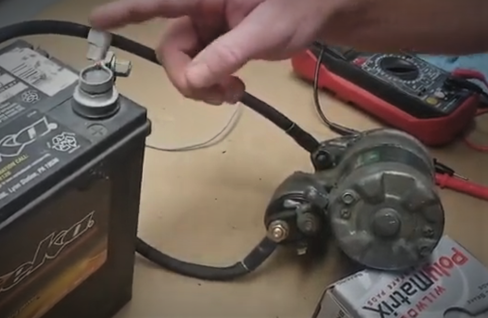
- Connect the Jumper Cables
The next step is to connect jumper cables to the starter motor. Find a red jumper cable, connect one end to the positive terminal of the battery and the other to the solenoid. Then, connect a black jumper cable to the negative terminal of the battery, while the other end is hooked into the starter motor’s lug on the main cylinder.
Tools for Testing a Starter Motor
– A multimeter
– Jumper cables
– A set of wrench and screwdrivers.
– A fully charged battery.
– Gloves and goggles for safety.
COMMON CAUSES OF FAILURE
Now that you know how to check if the starter motor is faulty, you may also be interested in characterizing the common causes of failure. Like a car battery, typically replaced every three to five years, a starter motor also has an expected lifespan of 100,000 to 150,000 miles. However, these components don’t fail solely due to wear and tear.
Here are some other reasons why a starter motor might suddenly fail.
1.EXPOSURE TO THE ELEMENTS
All car parts are expected to function properly under ideal conditions. Exposure to elements such as water and dirt could lead to corrosion and premature deterioration of metal parts. Water can short-circuit electrical components and remove protective lubrication, while dirt can cause corrosion and rust.
2. EXPOSURE TO EXTREME CONDITIONS.
Automotive components are expected to function under specific conditions and pressures. However, constant exposure to extreme heat or cold can cause starter motor and battery components to wear out much faster. It is important to follow regular and safe driving conditions to avoid excessively exposing the vulnerabilities of its components.
3. INCORRECT AND BAD INSTALLATION OF STARTER MOTOR
Regular maintenance is essential to extend the lifespan of a part or the whole of a car. This maintenance includes the correct installation of critical components such as electrical devices. Any misplacement or misalignment in simple connections can cause failure in the component.
TIPS FOR EXTENDING STARTER MOTOR LIFESPAN
TIP 1: Do not do repeated short starts
Tip 2: Ensure that your battery is in good condition.
Tip 3: Do regular car maintenance.
Tip 4: If you notice any car problem, fix it on time.
COST FOR REPLACING A STARTER
If you have a bad starter, you have the option of repairing it or replacing it. If you wish to replace it, here is what it will cost you.
– The cost of replacing parts of starters: $75 -$350
– Cost of labour: $150-$220
– A total estimate: $200-$220.
Note: This cost varies, depending on the model of car and your location.
FREQUENTLY ASKED QUESTION
- How long does a starter motor last?
A starter motor lasts between 120,000 to 150,000 miles.
- Will my car start with a bad starter?
This depends on the type of car. For automatic cars, it cannot start, but for manual cars, you may push it to start.
- What will it cost to fix a starter motor?
It cost between $200- $550.
Conclusion
The starter motor is a simple component of your car. It plays an important role in whether your car starts or not. Knowing how to test a starter motor demonstrates critical knowledge and skill should you encounter ignition problems. It is essential to learn how to check your car’s starter to diagnose any related problems that may arise. But most importantly, make sure you maintain your car to prevent these kinds of problems in the first place. Although checking starters can be an easy DIY task, it does not hurt to take extra precautions. When unsure, consult a trusted mechanic.
Read also:Throttle Position Sensor Symptoms
Have you ever pressed your accelerator but your car wouldn’t just respond the way it is expected to? That situation can be disturbing. The throttle position sensor is an important component in your car engine. This component monitors how open the throttle valve is depending on how much pressure is applied on the accelerator pedal. It controls how much air flows into the intake manifold, found in the engine. The engine control module, transmits how fast the throttle positions closes and open. The accelerator pedal sensor transmits the position of the accelerator pedal to the engine control unit (ECU). This information allows the ECU to determine the amount of acceleration the driver applies. When this sensor does not act as it should, it can affect the performance of car and even its fuel economy. This page explains the operating principle of modern accelerator pedal sensors and the symptoms that indicate a sensor malfunction. You will also learn how to have accelerator pedal sensors checked in a workshop.
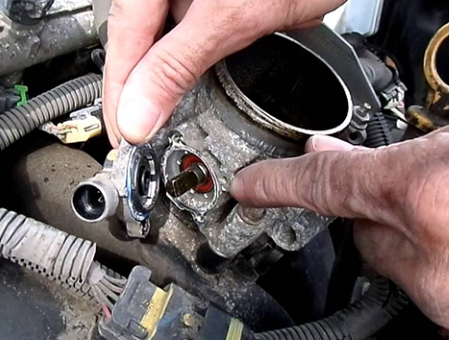
AN OVERVIEW OF THE THROTTLE POSITION SENSOR
The throttle position sensor is an essential component that informs the ECU about the precise opening of the throttle plate, allowing for accurate adjustment of the air-fuel mixture. In modern drive-by-wire systems, this sensor becomes even more critical, ensuring agile response and optimal fuel metering from the very first millisecond.
From its beginnings as an external and easily replaceable device, the throttle position sensor has evolved into designs integrated into the electronic throttle body, eliminating additional moving parts. This transition, driven since the 2000s by manufacturers such as Toyota and BMW, aims to improve the reliability and signal synchronization of next-generation injection systems.
You can find the throttle position sensor, mounted in the body of the throttle. It sends data to the ECU to adjust integral things like the fuel injection, ignition timing and air intake. Your car performs well, when this sensor is good.
Operating Principle of the Throttle Position Sensor
Accelerator Pedal Sensor: Operation
In modern vehicles, the proportion of electronic components is constantly increasing. This is due, among other reasons, to legal regulations, e.g., those related to reducing fuel consumption and emissions. Electronic components are also being used more and more to improve active and passive safety, as well as driving comfort. Among these components, the accelerator pedal sensor is a notable example.
For use in automobiles, contactless sensors, which operate on an inductive principle, are becoming increasingly common. This sensor consists of a stator, which includes an excitation coil, receiving coils, and evaluation electronics, and a rotor, formed by one or more closed loops with a specific geometry.
Applying an alternating voltage to the transmitting coil generates a magnetic field that induces a voltage in the receiving coils. The electronics process and evaluate these amplitudes, which are then sent as a direct current voltage to the control unit. The control unit evaluates the signal and transmits the corresponding pulse, e.g., to the throttle valve regulator. The properties of the voltage signal depend on the accelerator pedal position.
The Most Common Symptoms of Throttle Position Sensor
1. The Check Engine Light is One
This is the most common symptoms of a bad Throttle Sensor. It may indicate these common error codes; P0120, P0122 and P0121. Whenever you see any of these codes, you should know that there is an issue with the readings of your throttle sensor.
2.Slow Response to Acceleration
A slow response to acceleration is an indication that your car’s throttle position sensor is bad. In this instance, you will notice; weak acceleration, or even difficulty in overtaking another car.
In the event of a bad accelerator pedal sensor, some of the following symptoms may also appear:
- The engine only shows an increase in idle speed.
- The vehicle does not respond to accelerator pedal movements.
- The vehicle goes into “limp mode.”
- The check engine light illuminates.
3.Struggling to Change Gears
Gears are important in any car, be it manual or automatic. The Throttle Position sensor helps to control shifts in gears. But this is difficult in a bad sensor. If your sensor is bad, you will experience, delay in changing gears and transmission issues.
4. Low Fuel Economy
A bad position sensor can cause low fuel economy. In this case you may notice; reduced fuel mileage and bad engine performance.
5. Jerking While in Motion
If you notice sudden jerks while driving and a random change in acceleration, then you need to check your throttle position sensor.
Why the Throttle Position Sensor Fails
A malfunction can be caused by one of the following:
- Damaged connections or wiring at the accelerator pedal sensor.
- Lack of power and ground connection
Faulty evaluation electronics in the sensor
Build-up of dirts and carbon.
Using poor quality sensors for replacement.
Troubleshooting
- Accelerator Pedal Sensor Inspection
During troubleshooting, the following steps should be considered:
Read fault codes
- Visually inspect the accelerator pedal sensor for mechanical damage
- Visually inspect all relevant electrical connections and wiring to ensure they are secure and undamaged
- Test the sensor using an oscilloscope and a multimeter
Using a Mercedes-Benz A-Class (150) 1.7 as an example, the following describes all the troubleshooting steps, technical data, and illustrations to explain the fault location process.
Diagnose a Bad Throttle Position Sensor, how?
The following are confirmed ways for diagnosing a bad throttle position sensor:
- Use a Multmeter
This multimeter is used for measuring voltage changes when the throttle is in motion.
- Carry out a Visual Inspection
Visually inspect the sensor. Look out for bad or disconnected wires.
- Use an OBD-II Scanner
Use an OBD-II Scanner to check for any error codes relating to the throttle position sensor.
Step-By-Step Methods of Fixing a Bad Throttle Position Sensor
- First, clean dirts and carbon buildup on the sensor.
- Next, use a quality brand of throttle body cleaner to do a thorough clean up on it.
Sometimes, simply cleaning the position sensor may be all it needs to function properly again. But if the symptoms persist even after cleaning, consider replacing the sensor.
How to Replace a Bad Throttle Position Sensor
- First, carefully disconnect the battery.
- Second, remove the bad sensor.
- Third, gently replace the new sensor
- Finally, if necessary, calibrate the new sensor.
The Cost of Replacing a Throttle Position Sensor
The cost of replacing a throttle position sensor, depends on a number of factors, like the quality of sensor you want to use, the location and the labor cost. However, here is a typical estimated cost:
- Cost of sensor parts around, $25 -$200
- Cost of labour is about $65 -$150.
If you wish to do the replacement yourself, then, you will also need to include the cost of tools to use. You will need tools like a socket set and a screw driver.
Practical Maintenance Tips the Throttle Position Sensor
Maintenance always saves you money and time. Follow these practical tips to maintain your position sensor:
- Regularly clean the body parts of your throttle.
- Check the connections and wires.
- Only use good quality sensors when your throttle sensor is due for replacement.
- Do a periodic test to see how your throttle position sensor is doing. You may need a multimeter or an OBD-II scanner.
Frequently Asked Questions
1. Will I see error codes if my Throttle position sensor is bad?
Yes, you will. Error codes like P0121 and P0123 may be evident.
2. What happens if my position sensor is bad?
Poor fuel economy, sudden jerks while moving, and slow response to acceleration are common happening you would experience if your sensor is bad.
3. How do I clean my throttle sensor?
For thorough cleaning, use a good brand of throttle body cleaner.
4. Is replacing a bad position sensor easy?
Yes, with the right tools, you can easily do it.
5. How much does it cost to replace a bad throttle position sensor?
Around $150 -$250 for the sensor parts and labour cost.
6. What commonly causes a throttle position sensor to fail?
Accumulation of dirt, carbon build-up and faulty connections are a few things that can cause it to fail.
7.Can I replace a bad throttle position sensor myself?
Yes, you can easily replace it yourself, if you have the right tools.
Read also: Engine Oil Pressure Sensor
Conclusion
Conclusively, at a simple glance, the throttle position sensor may appear as a small and insignificant component of the engine. But, as you have seen from this article, it plays a significant role in making sure that your car is safe for use and its engine performs well. Some common symptoms of bad throttle position sensor include, slow response to acceleration, poor fuel economy and sudden jerks or surge while the car is in motion. Thankfully, both fixing and replacing a bad throttle position sensor is not so expensive. To fix a bad position sensor, you can simply clean the sensor or check the wiring for any disconnections. To replace a bad position sensor, first, remove your battery, disconnect wires and replace the throttle sensor with a new one. If you are already noticing any of the symptoms discussed in this article, do not wait till it get worse. Consult a trusted mechanic.
Also read:https://www.ctscorp.com/Products/Position-Sensors/Throttle-Position-Sensors

You are driving and you suddenly pull up to a stop sign but your car shakes when you brake. What can you do? Why does your car shake when you apply brakes? Do not be disturbed. Car shaking when braking is commonly due to worn-out brake rotors or worn-out brake pads. Brake vibration in cars is the vibration felt through the steering wheel and suspension when the brakes are applied at certain pressures and speeds. This shake can range from a barely noticeable to a more serious shake. While this is a serious issue in cars, it can be solved. In this article, we will preview the main causes of car shaking when braking and possible solutions and the cost of fixing this problem. .
CAUSES AND SOLUTIONS OF SHAKE DURING BRAKING
Shaking when braking is a major sign of bad brake rotors and pads. Other causes include, tire misalignment and overheating. The solutions to these problems are practical. They include properly aligning common causes of this problem are:
CAUSE 1: HUB BEARING OR DISC MISALIGNMENT
Shaking when braking is caused by a poorly adjusted brake disc that is misaligned with the hub bearing or caliper.
To help you identify if this is the case, here are some symptoms and solutions:
Check for rust or dirt on the hub bearing surface.
WHY? Rust or dirt causes poor contact between the disc and the hub bearing.
SOLUTION
- Remove the disc and clean both surfaces to remove rust and other contaminants.
Check for warping of the hub bearing contact surface due to excessive torque.
WHY? Using too high a torque on the positioning screw causes vibration during brake application.
- Replace the discs and avoid excessive torque.
Check for hub bearing deformation
WHY? Although rare, it is possible for bearings to become deformed. Bolting a disc to a deformed hub will always cause brake vibration. The same will occur if rust is not removed from the hub bearing surface before installing the disc.
- After installing a disc, always check the disc’s centering with a measuring instrument. If the run out is out of tolerance, reposition the disc in an alternative location until the run out is within tolerance. If the run out remains out of tolerance, the hub bearing must be serviced.
- Check if alloy wheels are mounted correctly
WHY?
A common cause of disc runout in recent years is the incorrect mounting of “one-size-fits-all” alloy wheels. Because the same wheel is used for multiple hub types and sizes, installers are using locating spacers on the wheel studs. If the spacer is lost or damaged, the wheel cannot be centered correctly.
- Place the centering gauge on the back of the disc while fitting the wheel and measure the runout. The gauge will only show the runout once the wheel is fitted and adjusted, and the wheel may need to be replaced.
CAUSE 2: OVERHEATING AND SEVERE DISC WARPING
Any significant temperature increase can cause the disc metal to warp in different areas. These “hot spots” cause intermittent contact between the brake pad and the disc, resulting in vibration. To help you identify if this is the case, here are some symptoms and solutions:
Check for Signs of Brake Abuse
WHY? Brake abuse is the most common reason for overheating. Discs are designed to cool quickly between braking applications. But when brakes are applied intensely in rapid succession, for example, during mountain driving, the discs don’t have enough time to dissipate the heat.
THE SOLUTIONS:
- Blue spots on the disc surface are a good indication of overheating. Discs that show blue spots or a darker color in some areas cannot be salvaged and MUST ALWAYS be replaced, along with the brake pads.
Check the quality of your brake pads.
WHY? Poor-quality brake pads can overheat very easily, especially during hard braking. Excessive heat from the pads can cause the rotors to overheat, leading to warping.
- Again, look for blue spots on the rotor surface. If none are found, inform the driver about the risks of using low-quality pads. ALWAYS replace brake pads and rotors when blue spots are visible on the rotor.
CAUSE 3: DISC THICKNESS VARIATION (DTV)
DTV is the variation in the thickness of the rotor surface. For effective braking, the rotor must have the same thickness across its entire surface. If there is an uneven friction surface, the brake pad will slip and regain contact with the rotor as it rotates. This causes brake judder. To help you identify if this is the case, here are some symptoms and solutions:
Check with the driver to see if the brakes have been properly bedded in.
WHY? To get the best performance from your brakes, it’s essential to follow the bedding-in procedure. By applying only moderate pressure to the brake pedal during the first few applications, an even layer of friction material is transferred from the pads to the disc. Properly bedding in the surfaces improves safety and prevents vibrations associated with brake disc vibration (DTV).
The Solution
Prevent The Problem
Prevention is better than cure. Whenever you install new brake pads, avoid hard braking for the first 200 km (125 miles). When improper bedding has resulted in slight brake disc vibration, re-batting the brakes may be sufficient. If this doesn’t realign the disc surfaces, the only solution is to replace the brake pads and discs.
Check if the caliper is stuck.
WHY? A stuck caliper piston or caliper sliding pin causes uneven forces to be applied to each side of the brake disc, creating uneven wear, or DTV.
- This problem is usually caused by rust or dirt. Therefore, proper maintenance of the stuck caliper is necessary to prevent the problem from recurring, and both the brake pads and discs should be replaced.
- Check for dirt or corrosion on the disc surface.
WHY? During braking, some of the friction material from the brake pads is transferred to the disc. But with lower-quality brake pads, deposits of friction material can adhere to the disc unevenly, changing the disc’s thickness and parallelism.
- If the DTV is minimal, removing the deposits with a brush or sandpaper and testing the brakes on the road may be sufficient. If this hasn’t realigned the surfaces, the only solution is to replace the pads and rotors.
Check for pad marks on the rotors.
WHY? If you keep the brake pedal pressed when the brakes overheat, pad material can become imprinted or welded onto the rotors. This will often be visible as the outline of a brake pad on the rotor surface.
- Removing the pad mark with a brush or sandpaper should be sufficient.
- Check for brake pad marks on the discs.
WHY? If you keep the brake pedal pressed when the brakes overheat, brake pad material can become imprinted or welded onto the discs. This imprint will often be visible as the outline of a brake pad on the disc surface.
- Removing the pad mark with a brush or sandpaper should be sufficient.
WAYS TO PREVENT YOUR CAR FROM SHAKING WHEN BRAKING
The following are practical ways to prevent your car from shaking when braking:
- Ensure that your rotors remain flat and maintain a smooth surface.
- Install new brake pads, when your brake pads get worn out.
- Damaged brake calipers result in uneven pressure in the braking system. Hence, check your brake calipers, and change it when you notice a damage.
- Drive carefully. Braking hard frequently can cause shaking in your braking system, eventually.
- Regularly go for tire alignment and balance.
- See a trusted mechanic for inspection.
HOW MUCH DOES IT COST TO FIX BRAKE SHAKE?
The cost of fixing brake shake in a car, depends on the component of the braking system that is faulty. For example, for:
– Brake rotors – $350-$600
– Brake pads – $400-$700
– Tire alignment: $65 – $200 (for all 4 tires)
Note: The cost includes labour.
Average cost ranges from $200 – to $1,200.
FREQUENTLY ASKED QUESTIONS
- If my car shakes when braking, when should I see a mechanic?
You should see a mechanic when the shakes are persistent, you perceive a burning smell when braking or when you notice that your brake is no longer effective.
- Can bad tires cause shaking?
Certainly, bad tires can cause shaking when braking.
- How much does it cost to fix brake vibration in my car?
Typically, to fix brake vibration in cars, is between $200 to $1,000 or more including cost of labor.
- Can I drive when my car shakes?
Simple answer, no. It is not recommended to drive if your car shakes when driving.
5. Why does my steering wheel shake when I brake at high speed?
Improper alignment of tire and suspension issues can cause car vibrations.
Read also: How to Clean a Catalytic Converter Safely and Effectively
CONCLUSION
Car vibration when braking is usually a sign that your brake rotor, pads or other components in the braking system may be faulty. To prevent your car from shaking, drive carefully, ensure that your tires are balanced and aligned, and replace worn out suspension components. To fix this problem, replace worn out brake pads or callipers and resurface or replace bad brake rotors. Whether the shake is minor or serious, see a trusted mechanic to check your car’s braking system.
Also read: https://bullet-automotive.com/is-your-car-shaking-when-you-brake-heres-why/
-

 Car Problems5 months ago
Crankshaft Pulley: Symptoms of Failure, Replacement Cost & Function
-

 DIY Fixes5 months ago
Engine Mount Replacement Cost
-

 Car Problems5 months ago
Cylinder Head Temperature Sensor: Function, Symptoms & Replacement Cost
-

 Car Problems5 months ago
How Much Is a Turbo Charger?
-

 Check Engine Light5 months ago
Camshaft Position Sensor Replacement
-

 Costs5 months ago
Catalytic Converter Replacement Cost
-

 Car Problems5 months ago
Best Catalytic Converter Cleaner
-

 Car Problems5 months ago
How to Clean a Catalytic Converter Safely and Effectively