Car Problems
Cylinder Head Temperature Sensor: Function, Symptoms & Replacement Cost
Fuel delivery, ignition timing, and overall engine safety are all significantly influenced by the cylinder head temperature sensor (CHT sensor), a tiny but crucial engine component. This sensor allows the engine to run effectively in both cold-start and high-temperature situations by continuously measuring the cylinder head’s temperature and sending real-time data to the engine management unit (ECU).
A malfunctioning cylinder head temperature sensor can result in instant drivability issues, such as hard starting, poor fuel economy, rough idling, or even engine overheating, in contrast to many engine parts that deteriorate gradually.
The accuracy of the CHT sensor is crucial for avoiding expensive engine damage because it is more significant than the coolant temperature sensor in some vehicles, particularly air-cooled and some European engines.
This blog post explains what a cylinder head temperature sensor is, how it functions, why it’s crucial, typical failure symptoms, diagnostic techniques, replacement costs, and maintenance advice.
This book will assist you in making well-informed decisions regarding your car’s engine temperature management system, whether you’re an enthusiast attempting to maintain optimal engine performance or a car owner trying to interpret a check engine light.

What Is a Cylinder Head Temperature Sensor?
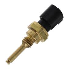
An engine-mounted temperature sensor called a cylinder head temperature sensor (CHT sensor) measures the temperature of the cylinder head metal itself, not the coolant passing through the engine.
The engine control unit (ECU) can precisely monitor engine heat levels thanks to this direct temperature monitoring, particularly in situations where coolant temperature alone does not give a full picture of engine operating temperature.
As an additional temperature sensor, the cylinder head temperature sensor is frequently utilized in air-cooled engines and some liquid-cooled automobiles.
The sensor must be designed to endure high temperatures while providing accurate data to the ECU since the cylinder head is subjected to intense heat during combustion. Since the majority of CHT sensors are thermistors, their electrical resistance varies with temperature.
Definition and Basic Function
The cylinder head temperature sensor’s main job is to let the ECU know how hot the cylinder head is at any given time. The ECU uses this data to modify a number of crucial engine parameters, such as:
-
Fuel injection timing and fuel mixture
-
Ignition timing
-
Idle speed during cold starts
-
Engine cooling fan operation (in some vehicles)
-
Emissions control strategies
The ECU may increase the fuel mixture to enhance warm-up and starting while the engine is cold. To avoid knocking, overheating, or engine damage, the ECU gradually leans the mixture and improves ignition timing as the cylinder head temperature increases.
Where the Cylinder Head Temperature Sensor Is Located
To precisely monitor metal temperature, the cylinder head temperature sensor is usually screwed directly into the cylinder head. Typical places to mount include:
-
Near the combustion chamber
-
Between cylinders
-
Close to the exhaust valve area
The sensor can malfunction over time because of its placement, which exposes it to extreme heat and vibration. In certain engines, the sensor is readily accessible from the top of the engine bay, but in others, it could be necessary to remove intake parts or engine covers.
How a Cylinder Head Temperature Sensor Works
Engine heat is transformed by the cylinder head temperature sensor into an electrical signal that the engine control unit (ECU) can decipher. The ECU heavily depends on this sensor’s input to perform real-time changes that keep the engine operating smoothly under all driving situations because temperature directly influences combustion efficiency and engine safety.
The ECU can react fast to cold starts, severe engine loads, or overheated circumstances since the majority of cylinder head temperature sensors are made to react swiftly to temperature changes. In engines that do not rely entirely on coolant temperature for thermal control, this quick reaction time is particularly crucial.
Sensor Design and Temperature Measurement
A cylinder head temperature sensor typically uses a Negative Temperature Coefficient (NTC) thermistor. This means:
-
High resistance at low temperatures
-
Low resistance at high temperatures
The internal resistance of the sensor decreases when the cylinder head heats up. Accurate measurement of cylinder head heat rather than fluid temperature is made possible by this change in resistance, which is proportionate to the temperature of the metal around the sensor.
To guarantee direct contact with engine metal, the sensor is threaded into the cylinder head and encased in a heat-resistant shell. It can measure actual combustion-related heat rather than averaged or delayed temperatures thanks to this architecture.
How Data Is Sent to the ECU
Based on its resistance, the cylinder head temperature sensor transmits a voltage signal to the ECU. This signal is continuously monitored by the ECU, which then compares it to temperature maps that have been preprogrammed. The ECU may, based on the readings:
-
Increase fuel delivery during cold starts
-
Reduce ignition timing to prevent engine knock
-
Activate engine cooling strategies
-
Trigger warning lights or fail-safe modes
The ECU may store a diagnostic fault code and turn on the check engine light if the signal is outside of the anticipated range.
Cylinder Head Temperature Sensor vs Engine Coolant Temperature Sensor
While both sensors are in charge of keeping an eye on engine temperature, the cylinder head temperature sensor (CHT) and the engine coolant temperature sensor (ECT) have different functions and give the engine control unit (ECU) different kinds of information. Accurate diagnosis, appropriate maintenance, and general engine dependability all depend on an understanding of their differences.
What the Cylinder Head Temperature Sensor Measures
The actual temperature of the cylinder head metal is measured by the cylinder head temperature sensor. It responds fast to heat produced during combustion since it is installed directly into the cylinder head. This enables the ECU to identify abrupt temperature spikes that might happen during lean air-fuel circumstances, high engine loads, or harsh acceleration. In engines where quick and accurate temperature feedback is needed to avoid overheating or detonation, the CHT sensor is particularly useful.
What the Engine Coolant Temperature Sensor Measures
The temperature of the engine coolant as it moves through the cooling system is measured by the engine coolant temperature sensor. In order to control cooling fans, warm-up enrichment, and emissions systems, this sensor offers a more consistent and averaged view of engine temperature. However, compared to a cylinder head temperature sensor, the ECT sensor reacts more slowly to abrupt temperature fluctuations since coolant absorbs heat gradually.
Response Time and Temperature Accuracy
Response time is one of the main distinctions between the two sensors. The cylinder head temperature sensor is quite accurate at identifying localized overheating since it responds to changes in combustion heat nearly instantaneously. On the other hand, because the coolant must first absorb heat and move through the engine, the coolant temperature sensor responds more slowly. This distinction explains why some engines use ECT sensors for long-term temperature control while relying on CHT sensors for immediate engine protection.
Effect on Fuel Injection and Ignition Timing
Though in distinct ways, both sensors have an impact on ignition timing and fuel injection. The ECU can adjust the air-fuel mixture and ignition timing depending on real-time combustion heat thanks to the cylinder head temperature sensor, especially during cold starts and high-load situations.
On the other hand, once normal operating temperature is reached, the coolant temperature sensor makes sure the engine runs smoothly and helps control fuel enrichment during warm-up. Poor fuel economy, harsh running, or trouble starting can result from a faulty reading from either sensor.
Engine Designs That Use Each Sensor
Because they don’t have a liquid cooling system, air-cooled engines mostly rely on cylinder head temperature sensors. While certain high-performance and European cars have both sensors, many liquid-cooled engines use coolant temperature sensors as the main temperature input. In certain situations, the ECU integrates information from the CHT and ECT sensors to improve overheating protection, fuel efficiency, and engine control.
Which Sensor Is More Critical?
Engine design determines the relative relevance of each sensor. However, when a cylinder head temperature sensor fails, the ECU lacks precise information regarding combustion heat, which might result in rapid drivability issues. Because of this, knowing each sensor’s function ensures a speedier diagnosis and avoids needless engine damage.
Why the Cylinder Head Temperature Sensor Is Important
Maintaining engine performance, efficiency, and long-term dependability depends heavily on the cylinder head temperature sensor. It gives the engine control unit (ECU) the precise information required to safeguard the engine in both typical and harsh running circumstances since it measures the real temperature of the cylinder head.
Role in Engine Fuel Management
Helping the ECU regulate the air-fuel mixture is one of the cylinder head temperature sensor’s main purposes. The sensor alerts the ECU to enrich the fuel mixture for a smoother warm-up and easier starting when the engine is cold. The ECU gradually leans the mixture to increase fuel efficiency and lower emissions as the cylinder head temperature rises. The engine may run excessively rich or too lean in the absence of precise temperature data, which would result in subpar performance and higher fuel usage.
Influence on Ignition Timing
Ignition timing is also influenced by the cylinder head temperature sensor. Engine knock or detonation may be more likely when cylinder head temperatures are high. When the sensor senses excessive heat, the ECU may delay ignition timing to avoid this. On the other hand, ideal ignition timing is maintained for maximum power and efficiency at typical operating temperatures. This equilibrium may be upset by a malfunctioning sensor, resulting in misfires, knocking, or decreased engine performance.
Preventing Engine Overheating
The sensor serves as an early warning system for overheating since it responds swiftly to sudden temperature fluctuations. This is particularly crucial in high-load driving scenarios including forceful acceleration, steep hill climbing, and towing. In order to prevent serious engine damage, the ECU can initiate precautionary measures like lowering engine power or turning on warning lights if excessive temperatures are detected.
Improving Emissions Control
Exhaust emissions are directly impacted by the ECU’s ability to maintain optimal combustion, which is made possible by accurate cylinder head temperature data. Emissions-control devices like the catalytic converter function more effectively when the engine is running at the proper temperature. Improper fuel supply due to a defective cylinder head temperature sensor might result in increased emissions and possibly fail an emissions test.
Supporting Overall Engine Longevity
The cylinder head temperature sensor greatly extends engine life by controlling fuel mixture, ignition timing, and thermal management. Regularly accurate temperature readings guarantee that the engine runs within safe bounds for the duration of its life, lessen the strain on internal parts, and avoid damage from overheating.
Common Symptoms of a Bad Cylinder Head Temperature Sensor
The engine control unit (ECU) may receive inaccurate or inconsistent temperature data when the cylinder head temperature sensor starts to malfunction. Even a tiny mistake can result in discernible drivability problems because the ECU mostly depends on this data to control fuel delivery and ignition timing. Early detection of these symptoms can help avoid expensive repairs and engine damage.
Check Engine Light Illumination
The check engine light is one of the first and most prevalent indicators of a malfunctioning cylinder head temperature sensor. The ECU registers a diagnostic fault code and activates the warning light when it finds temperature measurements that deviate from the anticipated range or do not match data from other sensors. If you ignore this warning, underlying issues may eventually get worse.
Hard Starting or No-Start Condition
Hard starting, particularly when the engine is cold, might be caused by a malfunctioning cylinder head temperature sensor. The ECU may cut fuel flow if the sensor indicates high temperatures incorrectly, which would make it harder for the engine to start. In extreme circumstances, an excessively lean air-fuel ratio may prevent the engine from starting at all.
Poor Fuel Economy
The engine may run excessively rich or too low due to inaccurate temperature readings, both of which have a detrimental effect on fuel efficiency. Higher fuel consumption and a discernible decrease in miles per gallon can result from an excessive fuel injection caused by a sensor that is stuck at a low temperature reading.
Engine Overheating or Running Too Cool
The ECU may not initiate precautionary measures if the sensor is unable to identify growing cylinder head temperatures, which raises the possibility of engine overheating. On the other hand, if a sensor is trapped at a high temperature, the engine may act as though it is overheated even when it is not, which would lead to subpar performance and needless power decrease.
Rough Idle and Engine Misfires
Inaccurate temperature data can cause hesitation, rough idling, or engine misfires by interfering with fuel injection and ignition timing. During cold starts or stop-and-go driving, when exact temperature regulation is crucial, these symptoms are frequently more apparent.
Reduced Engine Power or Limp Mode
In certain cars, the ECU may go to limp mode as a precaution if the cylinder head temperature sensor fails. In order to prevent internal components from overheating or being damaged, this lowers engine power, which causes the car to feel slow or unresponsive.
What Causes Cylinder Head Temperature Sensor Failure
Although cylinder head temperature sensors are designed to survive high temperatures and challenging engine conditions, a variety of mechanical, electrical, and environmental problems can eventually cause them to malfunction. You can maintain your engine operating dependably and avoid premature failure by being aware of these causes.
Heat Exposure and Thermal Stress
The sensor is subjected to intense heat from combustion since it is installed directly in the cylinder head. Thermal fatigue can result from the sensor material’s constant expansion and contraction brought on by high temperatures, which over time might reduce the sensor’s accuracy or cause it to stop working completely.
Electrical Issues and Wiring Damage
In order to transmit values to the ECU, the cylinder head temperature sensor needs a steady electrical connection. The engine control unit may not receive precise signals due to rusted connectors, damaged wiring, or short circuits. Intermittent or total sensor failure can result from the deterioration of wires and connectors caused by heat, vibration, and exposure to engine fluids over time.
Corrosion and Contamination
The sensor or its contacts may deteriorate if exposed to oil, coolant, dirt, or other engine impurities. Inaccurate temperature readings can result from electrical conductivity being disrupted by even a tiny amount of dirt or corrosion. This kind of damage can occasionally be accelerated by coolant leaks or oil seepage close to the sensor.
Age and Mileage Factors
Cylinder head temperature sensors deteriorate with time, just like any other automobile part. Although most sensors are meant to last between 80,000 and 120,000 miles, their lifespan may be shortened by severe engine use, extremely high or low temperatures, or inadequate maintenance. Before total failure, age-related degeneration frequently shows itself as inconsistent temperature readings or delayed response times.
Engine Modifications and Aftermarket Changes
Heat and stress levels may rise in engines that have been adjusted or altered for improved performance. Turbochargers and performance exhaust systems are examples of aftermarket components that can boost cylinder head temperatures above the original design limitations, hastening sensor degradation or leading to early failure.
Cylinder Head Temperature Sensor Trouble Codes (OBD-II)
On-Board Diagnostics (OBD-II) systems, which track sensor health and engine performance, are standard on contemporary cars. The ECU stores diagnostic trouble codes (DTCs) and may turn on the check engine light when a cylinder head temperature sensor fails. Accurate troubleshooting and prompt fixes depend on an understanding of these codes.
Common Diagnostic Codes
Some of the most frequent OBD-II codes related to cylinder head temperature sensors include:
-
P1285 – Cylinder Head Temperature Sensor Circuit Malfunction
-
P0117 – Engine Coolant Temperature Circuit Low Input (may affect CHT sensor in some models)
-
P0118 – Engine Coolant Temperature Circuit High Input
-
P0125 – Insufficient Coolant Temperature for Closed Loop Fuel Control (can be linked to CHT sensor issues)
These codes indicate problems ranging from sensor failure to wiring or connector issues. Each code helps pinpoint whether the problem is with the sensor itself, the circuit, or the ECU reading.
What Each Code Means
-
P1285: Indicates the cylinder head temperature sensor signal is outside the expected range. Often caused by sensor failure, wiring damage, or poor connector contact.
-
P0117 / P0118: Signals abnormal voltage from a temperature sensor, suggesting low or high temperature readings. May indicate short circuits, open circuits, or sensor degradation.
-
P0125: Triggered when the ECU believes the engine is not reaching optimal operating temperature. While this code usually relates to the coolant sensor, a faulty CHT sensor can contribute in engines that use both sensors.
Can You Drive With These Codes?
It is generally not advised to drive when the cylinder head temperature sensor is malfunctioning. The engine may continue to run, but the ECU loses important information for:
-
Fuel mixture adjustment
-
Ignition timing
-
Overheating protection
Poor performance, higher fuel consumption, and possible engine damage might result from this. The ECU may occasionally go into limp mode, which lowers engine output to avoid overheating. Early detection and resolution of these codes helps prevent later, more costly repairs.
How to Test a Cylinder Head Temperature Sensor
The engine control unit (ECU) receives precise temperature measurements from a cylinder head temperature (CHT) sensor when it is tested. Poor fuel economy, misfires, hard starts, and even engine overheating can be caused by a malfunctioning sensor. It is possible to ascertain whether the sensor needs to be cleaned, repaired, or replaced by conducting an appropriate test.
Tools Required
To test a cylinder head temperature sensor, you will need the following tools:
-
Digital multimeter – to measure resistance or voltage
-
OBD-II scanner – to read live temperature data from the ECU
-
Service manual – for manufacturer-specific resistance or voltage specifications
-
Gloves and basic hand tools – for safely accessing the sensor
Having the right tools ensures accurate testing and prevents damage to the sensor or wiring.
Step-by-Step Testing Procedure
-
Locate the Sensor: Refer to the vehicle’s service manual to find the cylinder head temperature sensor. It is usually threaded into the cylinder head or near the exhaust valve area.
-
Disconnect the Sensor: Carefully unplug the sensor from its electrical connector.
-
Measure Resistance: Set your multimeter to measure ohms and test the sensor across its terminals. Compare the reading to the manufacturer’s temperature-resistance chart.
-
Check Voltage Output: If your sensor operates with a voltage signal, reconnect it and measure the voltage while the engine warms up. The voltage should change gradually as the temperature increases.
-
Compare with Expected Values: Any readings significantly outside the manufacturer’s specified range indicate a faulty sensor.
Normal vs Abnormal Readings
-
Normal Readings: Resistance decreases as the temperature rises (for NTC thermistor sensors). Voltage gradually increases or decreases according to design specifications.
-
Abnormal Readings: A malfunctioning sensor is indicated by results that are significantly outside of the recommended range, unpredictable fluctuations, or no change in resistance or voltage with temperature changes.
Can You Drive With a Bad Cylinder Head Temperature Sensor?
In general, it is not advised to drive with a malfunctioning cylinder head temperature (CHT) sensor. A broken sensor can affect engine performance, fuel economy, and long-term dependability, even if some cars might still be able to operate. You can decide whether to keep driving or deal with the problem right away if you are aware of the risks.
Cylinder Head Temperature Sensor Replacement Cost
The cost of parts and labor for replacing a cylinder head temperature (CHT) sensor might vary based on the make, model, and engine architecture of the vehicle. Car owners can budget for repairs and choose between DIY and professional installation by being aware of the cost breakdown.
Average Replacement Cost in the U.S.
A cylinder head temperature sensor typically costs between $80 and $250 to replace. This covers labor costs as well as the sensor’s cost. The large range is caused by things like engine configuration, sensor accessibility, and whether the automobile is a high-performance model or a regular passenger car.
The sensor itself is reasonably priced in many cars; an OEM or premium aftermarket sensor typically costs between $20 and $80. However, depending on how simple it is to access the sensor, labor charges can range from $60 to $150.
Labor Cost Breakdown
Labor costs can be influenced by several factors:
-
Sensor accessibility: On some engines, the CHT sensor is located under intake components, requiring additional removal steps.
-
Engine type: Inline engines often provide easier access, while V-type engines or turbocharged engines may require more labor.
-
Mechanic rates: Labor rates vary by region and shop; dealerships typically charge more than independent repair shops.
Because labor can sometimes exceed the cost of the sensor itself, it’s important to get an estimate before authorizing repairs.
How Long Does a Cylinder Head Temperature Sensor Last?
The type of vehicle, engine conditions, and maintenance procedures all affect how long a cylinder head temperature (CHT) sensor lasts. These sensors do not survive forever, even though they are made to endure high temperatures and challenging engine settings. Car owners can anticipate replacement and prevent unexpected engine problems by being aware of their estimated lifespan.
Average Lifespan
Under typical driving circumstances, the majority of cylinder head temperature sensors last between 80,000 and 120,000 miles. Practically speaking, this means that an average car will last 8 to 12 years, depending on engine usage and climatic conditions. While less expensive aftermarket sensors might break down sooner, some premium OEM sensors might survive even longer.
Factors That Reduce Sensor Life
Several factors can shorten the lifespan of a cylinder head temperature sensor:
-
Extreme heat cycles: Frequent high-temperature operation or performance driving increases thermal stress.
-
Contamination: Oil, coolant leaks, dirt, and debris can corrode the sensor or damage electrical contacts.
-
Vibration: Constant engine vibrations can loosen connectors or damage the sensor housing.
-
Electrical issues: Wiring faults, shorts, or poor grounding can cause intermittent failures.
-
Engine modifications: Turbocharging, tuning, or aftermarket exhaust systems can raise cylinder head temperatures beyond original design limits.
Being aware of these risk factors allows owners to monitor the sensor and address minor issues before a complete failure occurs.
Preventive Maintenance Tips
To maximize the life of a cylinder head temperature sensor, consider the following maintenance practices:
-
Regular inspection: Check the sensor and its wiring during routine engine maintenance. Look for corrosion, loose connectors, or physical damage.
-
Keep the engine clean: Prevent oil, coolant, or dirt buildup around the sensor.
-
Address leaks promptly: Coolant or oil leaks near the sensor can accelerate wear and cause inaccurate readings.
-
Avoid extreme engine abuse: Excessive high-RPM driving or overheating situations can degrade the sensor faster.
You may assist guarantee accurate temperature readings and extend the sensor’s useful life by following these easy preventive measures.
Best Cylinder Head Temperature Sensor Brands
Selecting a reputable manufacturer is essential when replacing a cylinder head temperature (CHT) sensor in order to guarantee precise temperature readings, engine efficiency, and long-term durability. Although there are premium aftermarket and OEM (Original Equipment Manufacturer) brands, not all sensors function the same.
OEM Recommendations
OEM sensors are made to precisely match the make and model of the car. Typically, they provide:
-
Precise calibration for accurate readings
-
High reliability and longer lifespan
-
Warranty coverage when purchased through dealerships or authorized suppliers
Common OEM brands include:
-
Bosch – Widely used in European and Japanese vehicles, known for durability and accuracy
-
Denso – Common in Japanese cars, praised for fast response and consistent readings
-
Delphi – Used in many American vehicles, reliable under high-heat conditions
Although OEM sensors are usually more costly than aftermarket alternatives, their lifespan and performance can make the price worthwhile.
Trusted Aftermarket Brands
High-quality CHT sensors that work with many car manufacturers are available from a number of aftermarket brands:
-
Standard Motor Products (SMP) – Offers sensors with specifications similar to OEM units
-
ACDelco – Reliable for GM and other American vehicles, widely available
-
NGK/NTK – Known for high-temperature tolerance and fast response
-
Vemo and Wahler – Trusted for European vehicles
To prevent performance or lifetime problems, be sure the aftermarket sensor you select is made for your particular car and meets or surpasses OEM requirements.
Cylinder Head Temperature Sensor Maintenance
For precise engine temperature monitoring, effective operation, and long-term engine health, maintaining your cylinder head temperature (CHT) sensor is essential. Because the sensor works in a demanding environment with high temperatures, vibrations, and possible contamination, routine maintenance helps avoid early failure and expensive repairs.
Keep the Sensor and Wiring Clean
Reliable operation requires a clean sensor. The sensor’s readings may be affected by dirt, oil, or coolant leaks, which could result in erroneous data being transmitted to the ECU. When doing regular engine inspections:
-
Clean the sensor housing to remove any accumulated dirt or debris.
-
Inspect the electrical connector for corrosion or moisture that could disrupt the signal.
-
Check the wiring harness for frayed or damaged insulation, ensuring all connections are secure.
Accurate, reliable temperature readings from the sensor are ensured by maintaining cleanliness and tight connections.
Protect the Engine from Overheating
Controlling heat exposure is essential since the CHT sensor keeps an eye on cylinder head temperature to guard against engine damage:
-
Maintain the cooling system, including radiator, hoses, and coolant levels, to avoid excessive engine temperatures.
-
Avoid prolonged high-RPM or heavy-load driving without adequate cooling.
-
Address engine overheating immediately, as repeated exposure to extreme temperatures can degrade the sensor’s internal components.
In addition to protecting the sensor, limiting overheating also protects the engine from potential harm like blown gaskets or distorted heads.
Inspect the Sensor During Routine Engine Service
Examining the CHT sensor is a good idea if you undertake engine maintenance or remove parts close to the cylinder head:
-
Check for physical damage or corrosion that may affect performance.
-
Ensure wiring connections are tight and intact to prevent intermittent failures.
-
Clean the mounting area to avoid contamination that could affect readings.
Regular inspection can identify little problems before they become serious sensor failures, saving time and money on repairs.
Replace the Sensor at the First Sign of Trouble
CHT sensors have a limited lifespan and may eventually need to be replaced, even with proper maintenance. If you observe the following, think about changing the sensor:
-
Erratic or inconsistent temperature readings from the sensor.
-
Persistent check engine light with codes related to cylinder head temperature.
-
Engine performance issues, such as rough idling, misfires, overheating, or poor fuel economy.
In addition to protecting the engine and ensuring optimal performance, proactive replacement helps maintain precise temperature monitoring.
Frequently Asked Questions (FAQs) About Cylinder Head Temperature Sensors
Although cylinder head temperature (CHT) sensors are essential parts, many car owners frequently have concerns about their operation, symptoms, and replacement. You can maintain your engine, identify issues, and make wise repair decisions by being aware of these FAQs.
Is a Cylinder Head Temperature Sensor the Same as a Coolant Temperature Sensor?
No. Both sensors track distinct areas even though they both detect engine temperature. The CHT sensor provides quick feedback on combustion heat by measuring the cylinder head metal’s real temperature. A slower, averaged view of engine temperature is provided by the engine coolant temperature (ECT) sensor, which detects the temperature of the circulating coolant. For the best engine management, some cars make use of both sensors.
Can a Bad Cylinder Head Temperature Sensor Cause Overheating?
Yes! Inaccurate temperature readings from a malfunctioning sensor could prohibit the ECU from activating the cooling fan or making the necessary fuel adjustments. If this is not fixed, the engine may overheat, perform poorly, or possibly sustain damage.
How Many Cylinder Head Temperature Sensors Does a Car Have?
Each cylinder bank in the majority of cars equipped with CHT sensors has one. V-type engines may feature two sensors, one for each bank, but inline engines usually have just one. Additional sensors for improved temperature monitoring may also be included in some European or high-performance cars.
Can I Replace the Sensor Myself?
Yes, replacing an engine is frequently simple, however accessibility varies depending on the type of engine. For seasoned auto owners with the right tools, a service manual, and a basic understanding of mechanics, DIY replacement is doable. To guarantee proper torque and calibration, complicated engines or difficult-to-reach sensors might need to be installed by professionals.
Will a Bad Sensor Damage My Engine?
Ignoring a malfunctioning CHT sensor might result in the wrong fuel mixture, inaccurate ignition timing, and overheating, which can harm the cylinder head, pistons, or valves. Optimal performance is maintained and serious engine issues are avoided with prompt diagnosis and replacement.
How Can I Test My Cylinder Head Temperature Sensor?
You can test the sensor using:
-
An OBD-II scanner to read live temperature data and check for trouble codes.
-
A multimeter to measure resistance and compare it to manufacturer specifications.
-
Visual inspection for corrosion, damaged wiring, or physical sensor damage.
Accurate testing helps determine if the sensor is faulty or if wiring or ECU issues are causing problems.
Conclusion
A tiny but essential part that has a significant impact on engine performance, fuel economy, and long-term dependability is the cylinder head temperature (CHT) sensor. It protects the engine from overheating and damage by enabling the ECU to modify fuel delivery, ignition timing, and cooling techniques based on real-time temperature data from the cylinder head.
Maintaining smooth operation and avoiding expensive engine repairs can be achieved by identifying the signs of a failing sensor, carrying out the appropriate diagnostics, and replacing it as needed. The sensor’s lifespan can be increased and accurate readings can be guaranteed with routine examination, clean connections, and attention to engine temperature management.
In the end, keeping a healthy cylinder head temperature sensor is crucial to maximizing engine performance, safeguarding important parts, and attaining fuel efficiency, making it a crucial component of regular automotive maintenance.


Owning a car comes with lots of responsibilities. Part of owning a car is dealing with a lot of problems, from small to big breakdowns, both electrical and mechanical. You are most likely to experience more minor breakdowns due to faulty electrical components. Among the components that occasionally fail is the starter motor, which turns the engine during ignition. However, signs such as squealing or whining noise, or the presence of dashboard lights but no engine power, indicate a problem with the starter motor. Fortunately, checking a starter motor isn’t too complicated, and troubleshooting this type of problem can be a DIY job. Let’s consider the right procedure for checking your starter motor.
HOW THE STARTER MOTOR WORKS
Before we get into how to test a car jump starter, let’s understand how it works.
A starter motor draws power from the battery used and uses the engine’s flywheel to start the process of combustion. Starter motors are found in modern cars and replace the old manual method of starting engines with a hand crank. This makes starting the engine safer and more efficient. This car component uses a solenoid for sending power to the motor, a motor, and a pinion gear for engaging the engine with flywheel.
SIGNS OF A BAD STARTER MOTOR
If you notice the following warning signs, then your starter motor may be bad.
- A grinding noise.
- Burning or smoke smell.
- Dashboard lights may come on but the engine doesn’t crank.
- You hear a clicking sound when you try to put on the engine.
WAYS FOR TESTING THE STARTERS MOTOR
Although the starter motor is still a small component; it can be tested in several ways, not just one. After all, it doesn’t work on its own; it still needs a battery and other components to function correctly. This means the problem could be with the starter motor itself or with other parts.
The following are different ways to check your car’s starting system.
1.CHECK FOR SIGNS OF A STUCK PINION GEAR
The pinion gear of a starter motor is responsible for moving the crankshaft by engaging with the flywheel and turning it, and disengaging once the engine is running. As a moving part, the pinion gear can seize and stop working.
Here’s what you need to do to see if the pinion gear is causing a problem.
- Do a Visual Inspection
To test the starter motor without removing it, you will need to visually inspect for signs of a stuck pinion gear. When the headlights dim when you try to start the engine, it is a sign that the pinion gear is stuck on the flywheel.
You will also hear the sound of an engine trying to start, along with dimmed lights, when the pinion ear is faulty. However, if there’s a clicking sound without the noise of an engine trying to start, and the lights also dim, the problem is likely the battery. In this case, you should check the electrical components directly.
- Release The Stuck Pinion
Once you are sure the pinion gear is stuck, do not use the starter motor until you’ve freed it. Locate the square tab on the back of the starter cylinder and turn it to release the jam. If there is no such bathtub and you have a manual transmission, turn off the ignition, put it in second gear, release the handbrake, and rock the car back and forth until the pinion gear dislodges. If it has an automatic transmission, it is best to remove the starter motor and test it on a test bench.
-
CHECK IF THERE ARE ANY PROBLEMS WITH THE ELECTRICAL SYSTEM
In a car, there is what is called the “electrical trifecta”, made up of the battery, the alternator, and the starter motor. Each one complements the others in a mechanical and electrical cycle. The battery powers the starter motor, which turns the engine, and the alternator turns to recharge the battery.
When one of these components fails, it will likely affect the other components as well. Follow the steps below to check for electrical problems with the starter motor.
- Inspect the Battery for Loose Connections and Voltage
A simple visual inspection can easily identify faulty electrical connections. Try inspecting under the hood for loose wires or corrosion that might be restricting electrical flow. Clean the battery terminals and reconnect and disconnected wires. For more accurate inspection, check the voltage of the battery, if it shows signs of a problem.
- Examine the Solenoid
When there is no problem with the battery but your car won’t start, it’s likely a faulty solenoid. A starter solenoid is an electromagnet attached to the engine that’s prone to poor connections.
Once you’ve resolved any disconnections to the solenoid but the problem persists, you should perform a circuit test on this device. A test light won’t illuminate if there’s still a connection problem, but if it does, there is a problem with the solenoid or the starter motor itself. Depending on the result of your diagnosis, you can proceed with self-repair or take the component for professional work or parts replacement.
-
TEST YOUR STARTER
What is a bench test? First, bench tests should depend on your level of confidence in your abilities. If you are not that confident, you can leave the bench tests to the professionals.
Bench testing is a method for validating whether there are any problems with the starter motor. It involves removing or unbolting the motor from under the hood. Here are proper procedures for bench testing a starter motor.
- Remove the Starter Motor
How do you test a starter motor on a test bench?
– Start with disassembly.
– Disconnect all the starter motor wires.
– Unbolt the motor from the engine block.
– Be sure to label all the wires so you can reconnect them correctly during reassembly.
– Consulting your owner’s manual will also be helpful to avoid getting lost during the process.
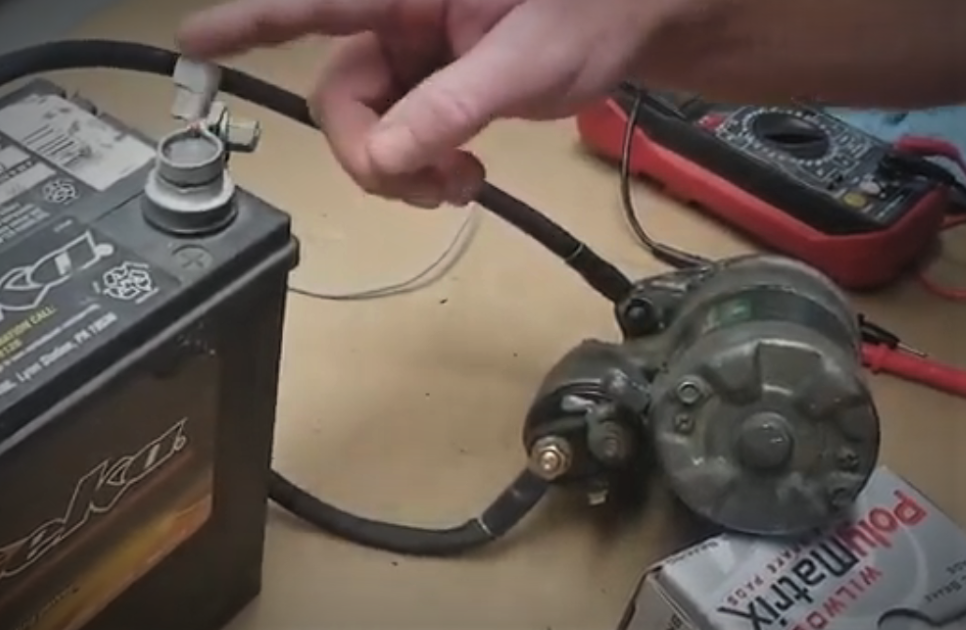
- Connect the Jumper Cables
The next step is to connect jumper cables to the starter motor. Find a red jumper cable, connect one end to the positive terminal of the battery and the other to the solenoid. Then, connect a black jumper cable to the negative terminal of the battery, while the other end is hooked into the starter motor’s lug on the main cylinder.
Tools for Testing a Starter Motor
– A multimeter
– Jumper cables
– A set of wrench and screwdrivers.
– A fully charged battery.
– Gloves and goggles for safety.
COMMON CAUSES OF FAILURE
Now that you know how to check if the starter motor is faulty, you may also be interested in characterizing the common causes of failure. Like a car battery, typically replaced every three to five years, a starter motor also has an expected lifespan of 100,000 to 150,000 miles. However, these components don’t fail solely due to wear and tear.
Here are some other reasons why a starter motor might suddenly fail.
1.EXPOSURE TO THE ELEMENTS
All car parts are expected to function properly under ideal conditions. Exposure to elements such as water and dirt could lead to corrosion and premature deterioration of metal parts. Water can short-circuit electrical components and remove protective lubrication, while dirt can cause corrosion and rust.
2. EXPOSURE TO EXTREME CONDITIONS.
Automotive components are expected to function under specific conditions and pressures. However, constant exposure to extreme heat or cold can cause starter motor and battery components to wear out much faster. It is important to follow regular and safe driving conditions to avoid excessively exposing the vulnerabilities of its components.
3. INCORRECT AND BAD INSTALLATION OF STARTER MOTOR
Regular maintenance is essential to extend the lifespan of a part or the whole of a car. This maintenance includes the correct installation of critical components such as electrical devices. Any misplacement or misalignment in simple connections can cause failure in the component.
TIPS FOR EXTENDING STARTER MOTOR LIFESPAN
TIP 1: Do not do repeated short starts
Tip 2: Ensure that your battery is in good condition.
Tip 3: Do regular car maintenance.
Tip 4: If you notice any car problem, fix it on time.
COST FOR REPLACING A STARTER
If you have a bad starter, you have the option of repairing it or replacing it. If you wish to replace it, here is what it will cost you.
– The cost of replacing parts of starters: $75 -$350
– Cost of labour: $150-$220
– A total estimate: $200-$220.
Note: This cost varies, depending on the model of car and your location.
FREQUENTLY ASKED QUESTION
- How long does a starter motor last?
A starter motor lasts between 120,000 to 150,000 miles.
- Will my car start with a bad starter?
This depends on the type of car. For automatic cars, it cannot start, but for manual cars, you may push it to start.
- What will it cost to fix a starter motor?
It cost between $200- $550.
Conclusion
The starter motor is a simple component of your car. It plays an important role in whether your car starts or not. Knowing how to test a starter motor demonstrates critical knowledge and skill should you encounter ignition problems. It is essential to learn how to check your car’s starter to diagnose any related problems that may arise. But most importantly, make sure you maintain your car to prevent these kinds of problems in the first place. Although checking starters can be an easy DIY task, it does not hurt to take extra precautions. When unsure, consult a trusted mechanic.
Read also:Throttle Position Sensor Symptoms
Have you ever pressed your accelerator but your car wouldn’t just respond the way it is expected to? That situation can be disturbing. The throttle position sensor is an important component in your car engine. This component monitors how open the throttle valve is depending on how much pressure is applied on the accelerator pedal. It controls how much air flows into the intake manifold, found in the engine. The engine control module, transmits how fast the throttle positions closes and open. The accelerator pedal sensor transmits the position of the accelerator pedal to the engine control unit (ECU). This information allows the ECU to determine the amount of acceleration the driver applies. When this sensor does not act as it should, it can affect the performance of car and even its fuel economy. This page explains the operating principle of modern accelerator pedal sensors and the symptoms that indicate a sensor malfunction. You will also learn how to have accelerator pedal sensors checked in a workshop.
AN OVERVIEW OF THE THROTTLE POSITION SENSOR
The throttle position sensor is an essential component that informs the ECU about the precise opening of the throttle plate, allowing for accurate adjustment of the air-fuel mixture. In modern drive-by-wire systems, this sensor becomes even more critical, ensuring agile response and optimal fuel metering from the very first millisecond.
From its beginnings as an external and easily replaceable device, the throttle position sensor has evolved into designs integrated into the electronic throttle body, eliminating additional moving parts. This transition, driven since the 2000s by manufacturers such as Toyota and BMW, aims to improve the reliability and signal synchronization of next-generation injection systems.
You can find the throttle position sensor, mounted in the body of the throttle. It sends data to the ECU to adjust integral things like the fuel injection, ignition timing and air intake. Your car performs well, when this sensor is good.
Operating Principle of the Throttle Position Sensor
Accelerator Pedal Sensor: Operation
In modern vehicles, the proportion of electronic components is constantly increasing. This is due, among other reasons, to legal regulations, e.g., those related to reducing fuel consumption and emissions. Electronic components are also being used more and more to improve active and passive safety, as well as driving comfort. Among these components, the accelerator pedal sensor is a notable example.
For use in automobiles, contactless sensors, which operate on an inductive principle, are becoming increasingly common. This sensor consists of a stator, which includes an excitation coil, receiving coils, and evaluation electronics, and a rotor, formed by one or more closed loops with a specific geometry.
Applying an alternating voltage to the transmitting coil generates a magnetic field that induces a voltage in the receiving coils. The electronics process and evaluate these amplitudes, which are then sent as a direct current voltage to the control unit. The control unit evaluates the signal and transmits the corresponding pulse, e.g., to the throttle valve regulator. The properties of the voltage signal depend on the accelerator pedal position.
The Most Common Symptoms of Throttle Position Sensor
1. The Check Engine Light is One
This is the most common symptoms of a bad Throttle Sensor. It may indicate these common error codes; P0120, P0122 and P0121. Whenever you see any of these codes, you should know that there is an issue with the readings of your throttle sensor.
2.Slow Response to Acceleration
A slow response to acceleration is an indication that your car’s throttle position sensor is bad. In this instance, you will notice; weak acceleration, or even difficulty in overtaking another car.
In the event of a bad accelerator pedal sensor, some of the following symptoms may also appear:
- The engine only shows an increase in idle speed.
- The vehicle does not respond to accelerator pedal movements.
- The vehicle goes into “limp mode.”
- The check engine light illuminates.
3.Struggling to Change Gears
Gears are important in any car, be it manual or automatic. The Throttle Position sensor helps to control shifts in gears. But this is difficult in a bad sensor. If your sensor is bad, you will experience, delay in changing gears and transmission issues.
4. Low Fuel Economy
A bad position sensor can cause low fuel economy. In this case you may notice; reduced fuel mileage and bad engine performance.
5. Jerking While in Motion
If you notice sudden jerks while driving and a random change in acceleration, then you need to check your throttle position sensor.
Why the Throttle Position Sensor Fails
A malfunction can be caused by one of the following:
- Damaged connections or wiring at the accelerator pedal sensor.
- Lack of power and ground connection
Faulty evaluation electronics in the sensor
Build-up of dirts and carbon.
Using poor quality sensors for replacement.
Troubleshooting
- Accelerator Pedal Sensor Inspection
During troubleshooting, the following steps should be considered:
Read fault codes
- Visually inspect the accelerator pedal sensor for mechanical damage
- Visually inspect all relevant electrical connections and wiring to ensure they are secure and undamaged
- Test the sensor using an oscilloscope and a multimeter
Using a Mercedes-Benz A-Class (150) 1.7 as an example, the following describes all the troubleshooting steps, technical data, and illustrations to explain the fault location process.
Diagnose a Bad Throttle Position Sensor, how?
The following are confirmed ways for diagnosing a bad throttle position sensor:
- Use a Multmeter
This multimeter is used for measuring voltage changes when the throttle is in motion.
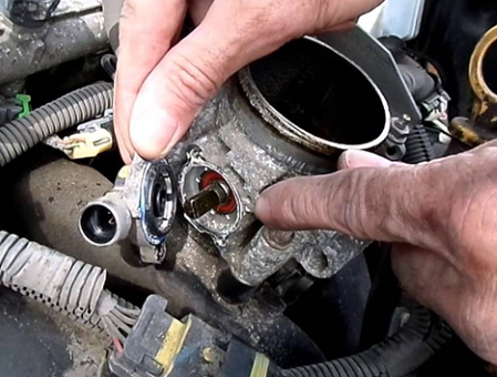
- Carry out a Visual Inspection
Visually inspect the sensor. Look out for bad or disconnected wires.
- Use an OBD-II Scanner
Use an OBD-II Scanner to check for any error codes relating to the throttle position sensor.
Step-By-Step Methods of Fixing a Bad Throttle Position Sensor
- First, clean dirts and carbon buildup on the sensor.
- Next, use a quality brand of throttle body cleaner to do a thorough clean up on it.
Sometimes, simply cleaning the position sensor may be all it needs to function properly again. But if the symptoms persist even after cleaning, consider replacing the sensor.
How to Replace a Bad Throttle Position Sensor
- First, carefully disconnect the battery.
- Second, remove the bad sensor.
- Third, gently replace the new sensor
- Finally, if necessary, calibrate the new sensor.
The Cost of Replacing a Throttle Position Sensor
The cost of replacing a throttle position sensor, depends on a number of factors, like the quality of sensor you want to use, the location and the labor cost. However, here is a typical estimated cost:
- Cost of sensor parts around, $25 -$200
- Cost of labour is about $65 -$150.
If you wish to do the replacement yourself, then, you will also need to include the cost of tools to use. You will need tools like a socket set and a screw driver.
Practical Maintenance Tips the Throttle Position Sensor
Maintenance always saves you money and time. Follow these practical tips to maintain your position sensor:
- Regularly clean the body parts of your throttle.
- Check the connections and wires.
- Only use good quality sensors when your throttle sensor is due for replacement.
- Do a periodic test to see how your throttle position sensor is doing. You may need a multimeter or an OBD-II scanner.
Frequently Asked Questions
1. Will I see error codes if my Throttle position sensor is bad?
Yes, you will. Error codes like P0121 and P0123 may be evident.
2. What happens if my position sensor is bad?
Poor fuel economy, sudden jerks while moving, and slow response to acceleration are common happening you would experience if your sensor is bad.
3. How do I clean my throttle sensor?
For thorough cleaning, use a good brand of throttle body cleaner.
4. Is replacing a bad position sensor easy?
Yes, with the right tools, you can easily do it.
5. How much does it cost to replace a bad throttle position sensor?
Around $150 -$250 for the sensor parts and labour cost.
6. What commonly causes a throttle position sensor to fail?
Accumulation of dirt, carbon build-up and faulty connections are a few things that can cause it to fail.
7.Can I replace a bad throttle position sensor myself?
Yes, you can easily replace it yourself, if you have the right tools.
Read also: Engine Oil Pressure Sensor
Conclusion
Conclusively, at a simple glance, the throttle position sensor may appear as a small and insignificant component of the engine. But, as you have seen from this article, it plays a significant role in making sure that your car is safe for use and its engine performs well. Some common symptoms of bad throttle position sensor include, slow response to acceleration, poor fuel economy and sudden jerks or surge while the car is in motion. Thankfully, both fixing and replacing a bad throttle position sensor is not so expensive. To fix a bad position sensor, you can simply clean the sensor or check the wiring for any disconnections. To replace a bad position sensor, first, remove your battery, disconnect wires and replace the throttle sensor with a new one. If you are already noticing any of the symptoms discussed in this article, do not wait till it get worse. Consult a trusted mechanic.
Also read:https://www.ctscorp.com/Products/Position-Sensors/Throttle-Position-Sensors

You are driving and you suddenly pull up to a stop sign but your car shakes when you brake. What can you do? Why does your car shake when you apply brakes? Do not be disturbed. Car shaking when braking is commonly due to worn-out brake rotors or worn-out brake pads. Brake vibration in cars is the vibration felt through the steering wheel and suspension when the brakes are applied at certain pressures and speeds. This shake can range from a barely noticeable to a more serious shake. While this is a serious issue in cars, it can be solved. In this article, we will preview the main causes of car shaking when braking and possible solutions and the cost of fixing this problem. .
CAUSES AND SOLUTIONS OF SHAKE DURING BRAKING
Shaking when braking is a major sign of bad brake rotors and pads. Other causes include, tire misalignment and overheating. The solutions to these problems are practical. They include properly aligning common causes of this problem are:
CAUSE 1: HUB BEARING OR DISC MISALIGNMENT
Shaking when braking is caused by a poorly adjusted brake disc that is misaligned with the hub bearing or caliper.
To help you identify if this is the case, here are some symptoms and solutions:
Check for rust or dirt on the hub bearing surface.
WHY? Rust or dirt causes poor contact between the disc and the hub bearing.
SOLUTION
- Remove the disc and clean both surfaces to remove rust and other contaminants.
Check for warping of the hub bearing contact surface due to excessive torque.
WHY? Using too high a torque on the positioning screw causes vibration during brake application.
- Replace the discs and avoid excessive torque.
Check for hub bearing deformation
WHY? Although rare, it is possible for bearings to become deformed. Bolting a disc to a deformed hub will always cause brake vibration. The same will occur if rust is not removed from the hub bearing surface before installing the disc.
- After installing a disc, always check the disc’s centering with a measuring instrument. If the run out is out of tolerance, reposition the disc in an alternative location until the run out is within tolerance. If the run out remains out of tolerance, the hub bearing must be serviced.
- Check if alloy wheels are mounted correctly
WHY?
A common cause of disc runout in recent years is the incorrect mounting of “one-size-fits-all” alloy wheels. Because the same wheel is used for multiple hub types and sizes, installers are using locating spacers on the wheel studs. If the spacer is lost or damaged, the wheel cannot be centered correctly.
- Place the centering gauge on the back of the disc while fitting the wheel and measure the runout. The gauge will only show the runout once the wheel is fitted and adjusted, and the wheel may need to be replaced.
CAUSE 2: OVERHEATING AND SEVERE DISC WARPING
Any significant temperature increase can cause the disc metal to warp in different areas. These “hot spots” cause intermittent contact between the brake pad and the disc, resulting in vibration. To help you identify if this is the case, here are some symptoms and solutions:
Check for Signs of Brake Abuse
WHY? Brake abuse is the most common reason for overheating. Discs are designed to cool quickly between braking applications. But when brakes are applied intensely in rapid succession, for example, during mountain driving, the discs don’t have enough time to dissipate the heat.
THE SOLUTIONS:
- Blue spots on the disc surface are a good indication of overheating. Discs that show blue spots or a darker color in some areas cannot be salvaged and MUST ALWAYS be replaced, along with the brake pads.
Check the quality of your brake pads.
WHY? Poor-quality brake pads can overheat very easily, especially during hard braking. Excessive heat from the pads can cause the rotors to overheat, leading to warping.
- Again, look for blue spots on the rotor surface. If none are found, inform the driver about the risks of using low-quality pads. ALWAYS replace brake pads and rotors when blue spots are visible on the rotor.
CAUSE 3: DISC THICKNESS VARIATION (DTV)
DTV is the variation in the thickness of the rotor surface. For effective braking, the rotor must have the same thickness across its entire surface. If there is an uneven friction surface, the brake pad will slip and regain contact with the rotor as it rotates. This causes brake judder. To help you identify if this is the case, here are some symptoms and solutions:
Check with the driver to see if the brakes have been properly bedded in.
WHY? To get the best performance from your brakes, it’s essential to follow the bedding-in procedure. By applying only moderate pressure to the brake pedal during the first few applications, an even layer of friction material is transferred from the pads to the disc. Properly bedding in the surfaces improves safety and prevents vibrations associated with brake disc vibration (DTV).
The Solution
Prevent The Problem
Prevention is better than cure. Whenever you install new brake pads, avoid hard braking for the first 200 km (125 miles). When improper bedding has resulted in slight brake disc vibration, re-batting the brakes may be sufficient. If this doesn’t realign the disc surfaces, the only solution is to replace the brake pads and discs.
Check if the caliper is stuck.
WHY? A stuck caliper piston or caliper sliding pin causes uneven forces to be applied to each side of the brake disc, creating uneven wear, or DTV.
- This problem is usually caused by rust or dirt. Therefore, proper maintenance of the stuck caliper is necessary to prevent the problem from recurring, and both the brake pads and discs should be replaced.
- Check for dirt or corrosion on the disc surface.
WHY? During braking, some of the friction material from the brake pads is transferred to the disc. But with lower-quality brake pads, deposits of friction material can adhere to the disc unevenly, changing the disc’s thickness and parallelism.
- If the DTV is minimal, removing the deposits with a brush or sandpaper and testing the brakes on the road may be sufficient. If this hasn’t realigned the surfaces, the only solution is to replace the pads and rotors.
Check for pad marks on the rotors.
WHY? If you keep the brake pedal pressed when the brakes overheat, pad material can become imprinted or welded onto the rotors. This will often be visible as the outline of a brake pad on the rotor surface.
- Removing the pad mark with a brush or sandpaper should be sufficient.
- Check for brake pad marks on the discs.
WHY? If you keep the brake pedal pressed when the brakes overheat, brake pad material can become imprinted or welded onto the discs. This imprint will often be visible as the outline of a brake pad on the disc surface.
- Removing the pad mark with a brush or sandpaper should be sufficient.
WAYS TO PREVENT YOUR CAR FROM SHAKING WHEN BRAKING
The following are practical ways to prevent your car from shaking when braking:
- Ensure that your rotors remain flat and maintain a smooth surface.
- Install new brake pads, when your brake pads get worn out.
- Damaged brake calipers result in uneven pressure in the braking system. Hence, check your brake calipers, and change it when you notice a damage.
- Drive carefully. Braking hard frequently can cause shaking in your braking system, eventually.
- Regularly go for tire alignment and balance.
- See a trusted mechanic for inspection.
HOW MUCH DOES IT COST TO FIX BRAKE SHAKE?
The cost of fixing brake shake in a car, depends on the component of the braking system that is faulty. For example, for:
– Brake rotors – $350-$600
– Brake pads – $400-$700
– Tire alignment: $65 – $200 (for all 4 tires)
Note: The cost includes labour.
Average cost ranges from $200 – to $1,200.
FREQUENTLY ASKED QUESTIONS
- If my car shakes when braking, when should I see a mechanic?
You should see a mechanic when the shakes are persistent, you perceive a burning smell when braking or when you notice that your brake is no longer effective.
- Can bad tires cause shaking?
Certainly, bad tires can cause shaking when braking.
- How much does it cost to fix brake vibration in my car?
Typically, to fix brake vibration in cars, is between $200 to $1,000 or more including cost of labor.
- Can I drive when my car shakes?
Simple answer, no. It is not recommended to drive if your car shakes when driving.
5. Why does my steering wheel shake when I brake at high speed?
Improper alignment of tire and suspension issues can cause car vibrations.
Read also: How to Clean a Catalytic Converter Safely and Effectively
CONCLUSION
Car vibration when braking is usually a sign that your brake rotor, pads or other components in the braking system may be faulty. To prevent your car from shaking, drive carefully, ensure that your tires are balanced and aligned, and replace worn out suspension components. To fix this problem, replace worn out brake pads or callipers and resurface or replace bad brake rotors. Whether the shake is minor or serious, see a trusted mechanic to check your car’s braking system.
Also read: https://bullet-automotive.com/is-your-car-shaking-when-you-brake-heres-why/
-

 Car Problems5 months ago
Crankshaft Pulley: Symptoms of Failure, Replacement Cost & Function
-

 DIY Fixes5 months ago
Engine Mount Replacement Cost
-

 Car Problems5 months ago
How Much Is a Turbo Charger?
-

 Car Problems5 months ago
Variable Valve Timing Solenoid – Symptoms, Location, Function & Replacement Cost
-

 Check Engine Light5 months ago
Camshaft Position Sensor Replacement
-

 Costs5 months ago
Catalytic Converter Replacement Cost
-

 Car Problems5 months ago
Best Catalytic Converter Cleaner
-

 Car Problems5 months ago
How to Clean a Catalytic Converter Safely and Effectively